Z97 Mini-ITX Review at $140: ASRock, MSI and GIGABYTE
by Ian Cutress on July 23, 2014 3:00 AM EST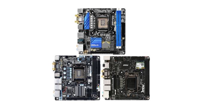
With every new chipset release, a large part of the community is always interested in the smaller form factor builds. Building a small yet powerful system seems to be an expanding niche, and for Intel’s Z97 platform we took three of the cheaper mini-ITX motherboards to see how they compare. The ASRock Z97E-ITX/AC, the MSI Z97I AC and the GIGABYTE Z97N-WIFI are all between $130 and $140, all feature 802.11ac support but vary in other connectivity, ease of use and their packages. We compared all three.
Z97 Mini-ITX Overview
What does the average user want from a mini-ITX system? Is there such a thing as an average user, or are all mini-ITX builds aimed at niche categories? Even these questions can be difficult to pin down, so we have to look at the basics for a 17cm square focal point.
Mini-ITX builds are typically not the center for overclocking, although they should be designed to house the most powerful processors (at least at stock). Two memory slots limits the memory capacity to 16 GB, which for VM use limits anything other than a simple virtualization environment with a handful of instances. The PCIe 3.0 x16 slot is usually a big plus, allowing gamers to equip the best single GPU card into a small system, or for home NAS builds to implement a RAID card, or for TV Tuner/HTPC applications. To date, I have built four mini-ITX systems for friends and family. My father uses one on the integrated graphics for a home/email/basic photo and video editing machine, while my brother has a nice discrete GPU for gaming on a single monitor. I own the other two, one on basic HTPC/streaming duty and the other as part of a makeshift NAS. Each of these four systems uses a different motherboard for requirements: the basic home-use machine uses an mSATA drive, the NAS has dual NICs, the HTPC has 2T2R 802.11ac WiFi and the gaming system has pretty lights for the see-through panel.
With the $130-$140 motherboards we are testing today, we could try and fit them into these four categories based on their hardware, functionality and performance. Being very close in price means that one motherboard will swap in a feature at the expense of another, so one would expect a lot of tit-for-tat between the manufacturers. Of course, anything in the box or on the software side could sweeten the deal, but it all depends if they end up being focused on one niche or a jack-of-all-trades.
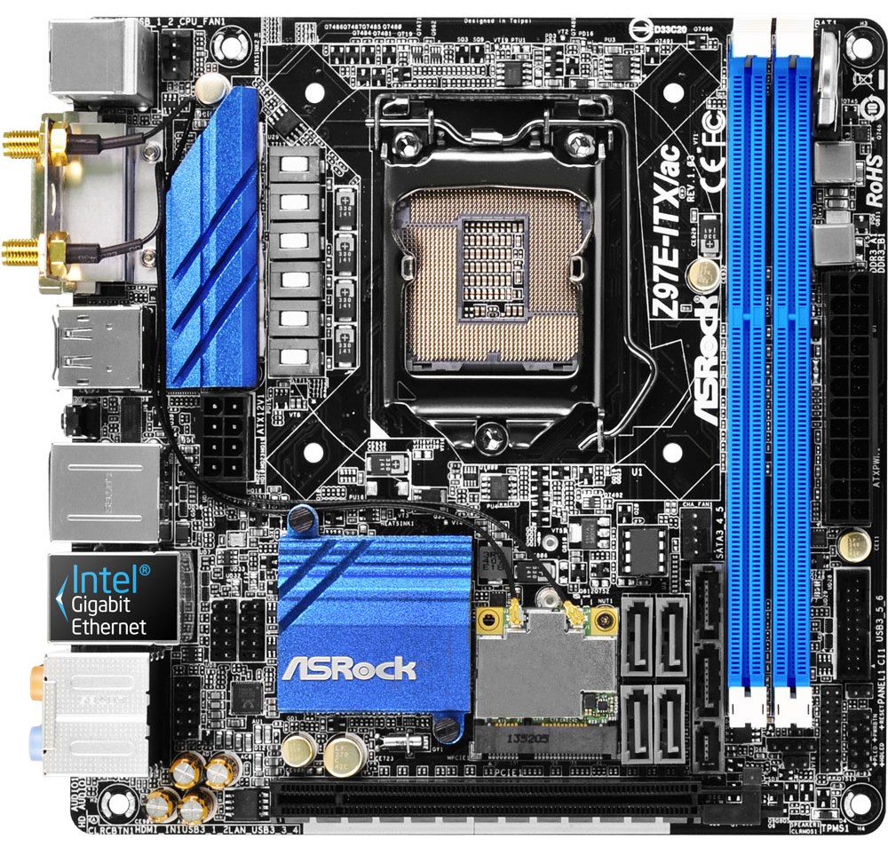
ASRock Z97E-ITX/AC Visual Inspection
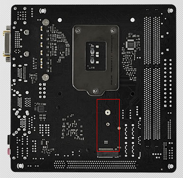
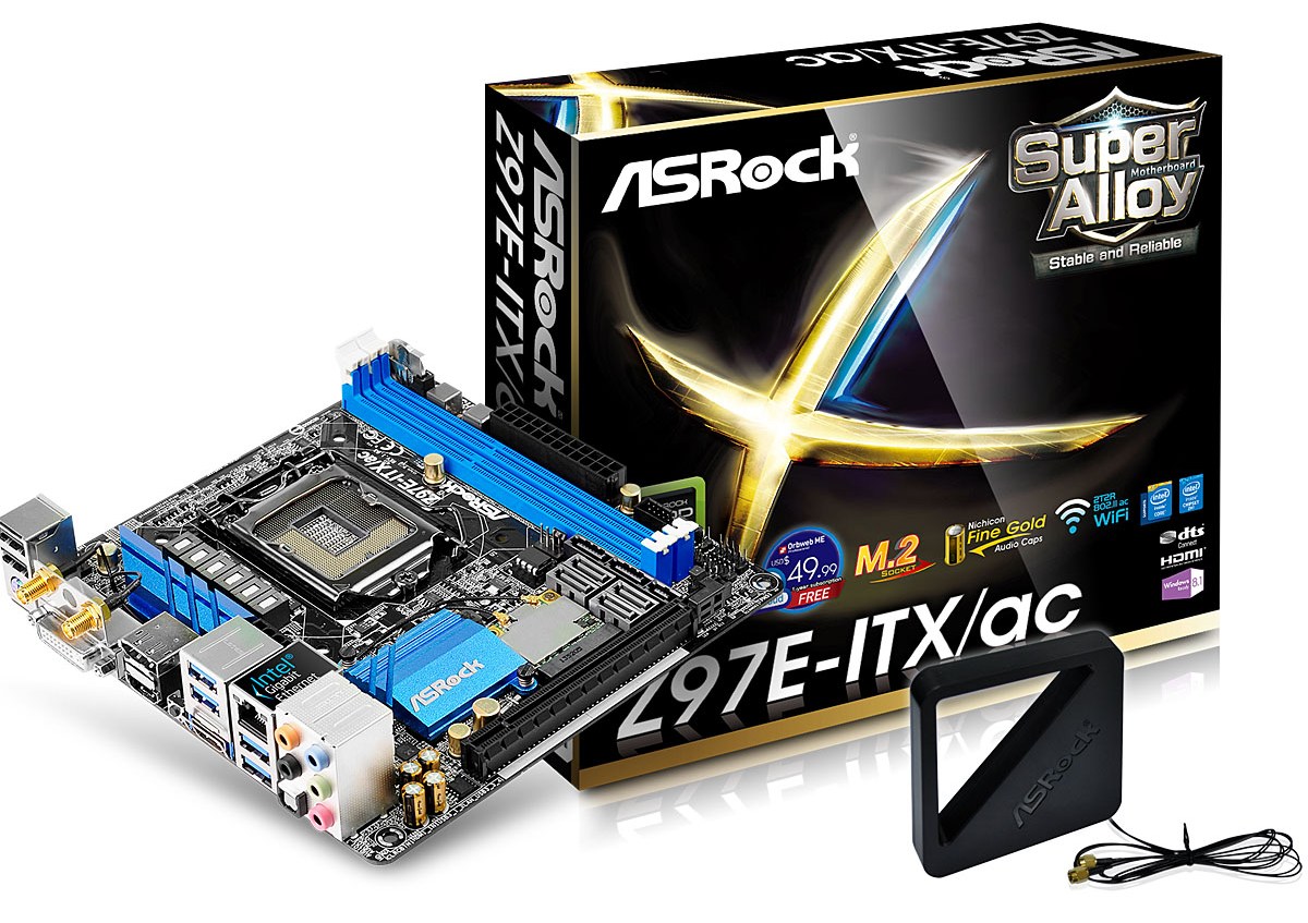
The first motherboard on the test bed was the ASRock Z97E-ITX/AC. In the past couple of generations, ASRock has done something slightly different to the others and it appears again on the Z97 model: a storage option on the rear of the motherboard. Usually when I mention this to people, the answer comes back ‘does this not touch the case?’ My answer comes back as ‘depends how big your stand-offs are’. The Z77 model with an mSATA equipped has no problems in a Bitfenix Prodigy, for example. Where the Z97E-ITX/AC differs for this generation is the switch from mSATA to M.2 on the rear.
The M.2 on the rear is only applicable for 30mm and 42mm, which is actually rather short, due to the orientation. As this is a PCIe and SATA capable M.2, this opens up the drive potential, however I feel the migration of the majority of motherboards to 80+mm drives might make the lower dimension models harder to find (as well as in lower capacities), making ASRock’s solution niche in more ways than one.
The primary design route of the Z97E-ITX/AC is similar to that of the predecessors. We get a top oriented socket to allow for larger coolers north to south, although the left to right spacing of the socket might obstruct the combination of large CPU heatsink and large DRAM heatsinks. The 6-phase power delivery has the ASRock styled heatsink, and the two fan headers are found at opposite ends of the socket – one top left and the other bottom right.
My first two issues with this board related to the number of fan headers (premium motherboards are getting three, even if two are connected together), and the second is with the 8-pin CPU power connector placement. One of the more prominent issues I have echoed with mini-ITX design is this placement, which (in my opinion) should be anywhere BUT the middle of the motherboard near the rear-IO. This is one of the worst places, because the cable to put in that port has to either navigate around a CPU heatsink, come across the DRAM and around a CPU heatsink or navigate over a PCIe device. Other motherboard manufacturers have recognized this, and oriented their power connectors nearer the edges of the board, but ASRock is still behind. I will not accept ‘ease of routing’ as an excuse here, especially if the engineers are putting M.2 slots on the rear of the motherboard.
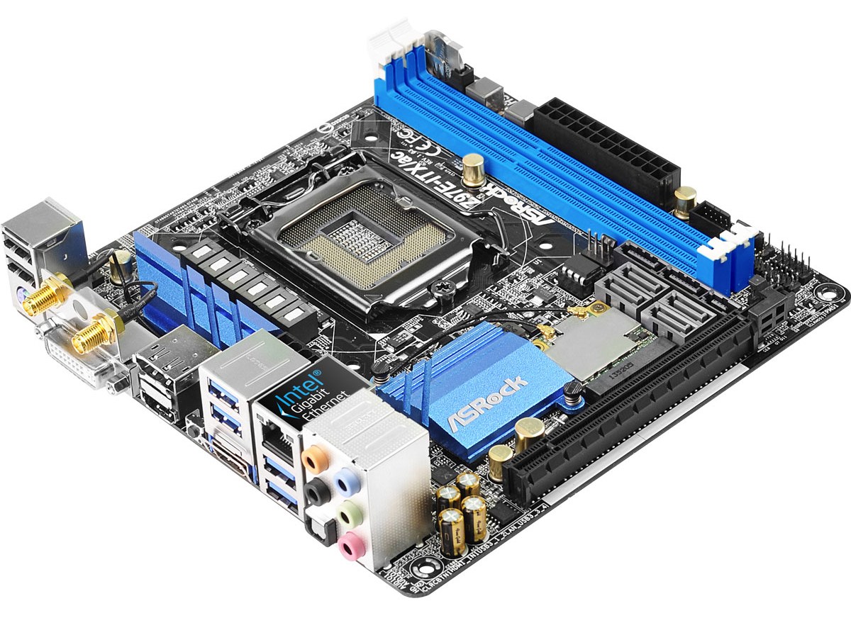
The DRAM slots use a single sided latch mechanism on the bottom of the board so as to not interfere with any GPU, although users should ensure that all the memory is fitted properly. On the top right of the board is the motherboard battery, set up in this location and standing up on the motherboard in order to save space. The 24-pin power connector is underneath, followed by the USB 3.0 header, front panel header and TPM header.
The location of the SATA ports between the DRAM and the mini-PCIe module is such that we get four SATA 6 Gbps in grey, two SATA 6 Gbps in black, and these last two ports form part of a SATA Express connector. One of the issues with this arrangement is the removal of devices with locking cables, requiring the user to disconnect other cables, or due to the location also requiring the DRAM or the GPU to be moved in order to get a hand in.
It should be noted that the SATAe connector, the two SATA 6 Gbps ports in black and the M.2 slot on the rear are all on a switch, thus using one will disable the other two. Unfortunately this is a limitation of the Intel chipset, and the lack of drives on the market for either of the PCIe storage options does not make the selection easier.
The mini-PCIe connector holds the included 802.11ac 2T2R WiFi module, and the two antenna points on the module are connected to the rear IO via internal wires. This is next to the chipset with a small heatsink, two USB 2.0 ports and the front panel audio port. The ASRock mini-ITX motherboard is a little different to the other two as the audio codec used is the better rated Realtek ALC1150 rather than the ALC892.
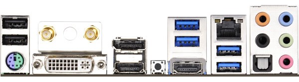
The rear panel gives a combination PS/2 port, two USB 2.0 ports, the combination DVI-I port, two antenna mounting points, both a HDMI-In and a HDMI-Out (for pass-through), DisplayPort 1.2, a ClearCMOS button, four USB 3.0 ports, the Intel I218-V gigabit Ethernet port and the audio jacks.
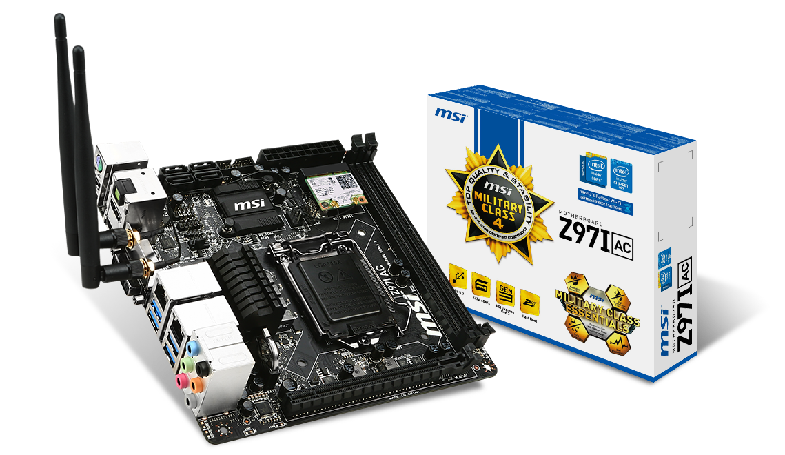
MSI Z97I AC Visual Inspection
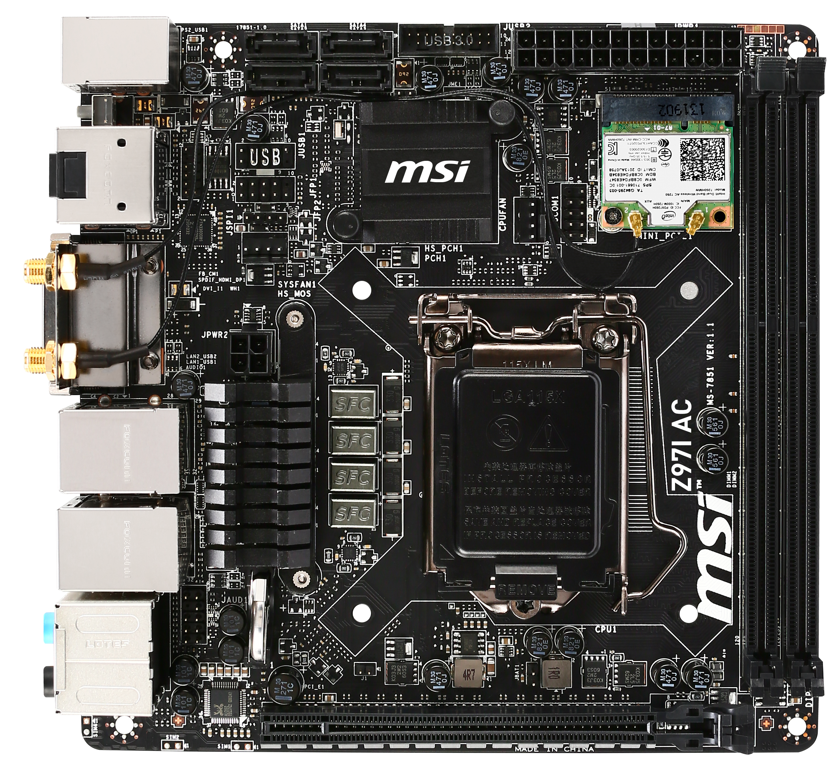
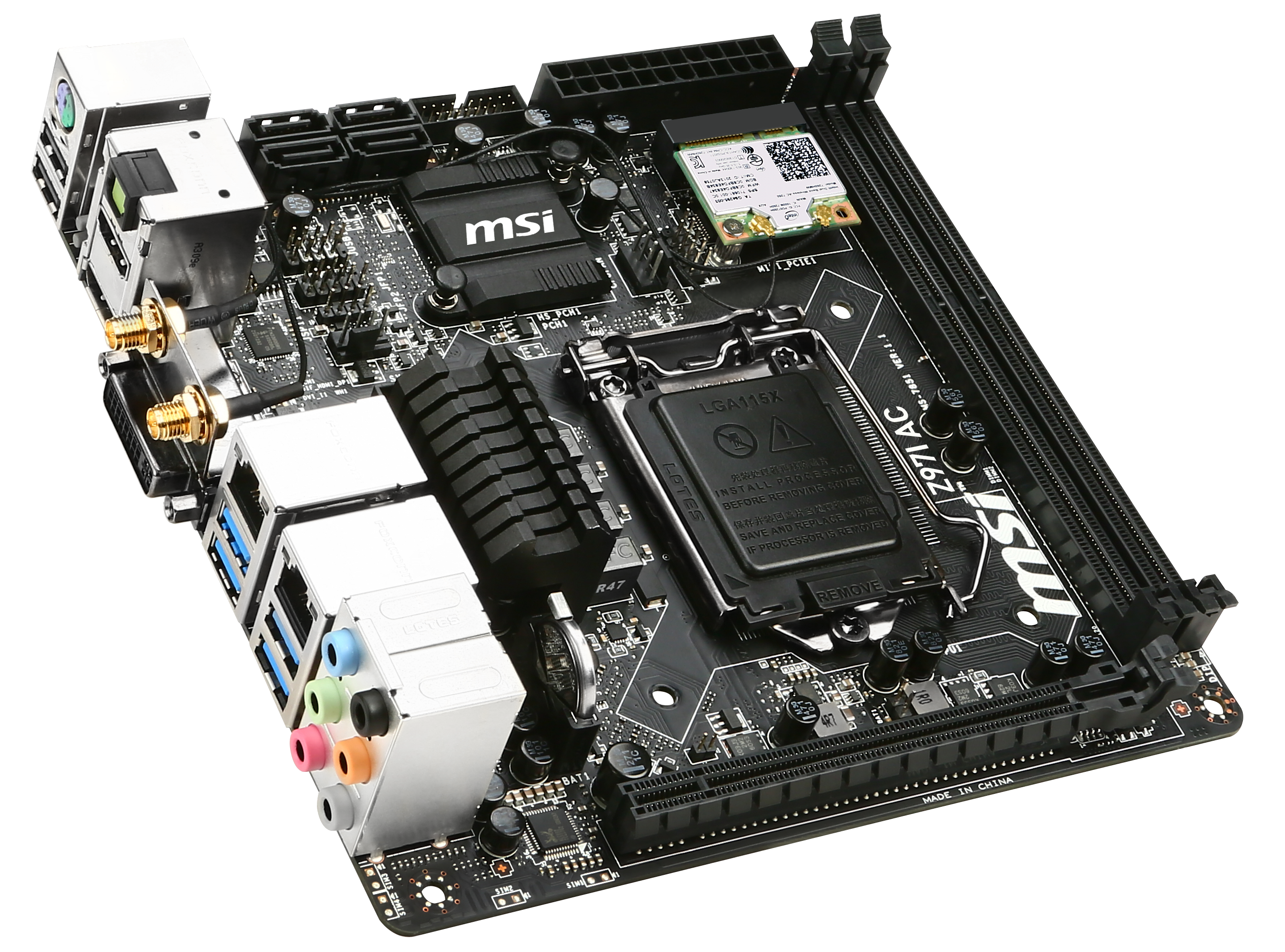
The first thing that immediately jumps out at me on the MSI Z97I AC is the position of the 4-pin CPU power connector. We find it just behind the rear panel, in the middle of the motherboard and slightly to the left. I have rallied for several generations now that this is perhaps the worst place to have this power connector. Any cable coming into this connector has to either jump over the SATA ports and front panel ports, jump over the DRAM then around the CPU heatsink, or jump over the graphics card. All three of these possibilities cause nightmares for cable management, and I would like this position to stop – now.
So the argument for having this power connector here is because the CPU socket is lower down on the motherboard, allowing the connectors related to the chipset space at the top. The second reason is one of cost – moving the DRAM inwards and placing connectors on the outside requires more PCB layers, and moving from a four layer to a six layer adds 30-50% cost to the PCB, depending on the quality of PCB used. At some point we are going to have to reach a happy medium: I believe there is a solution to a $130 motherboard having the connectors in decent places and the motherboard still retaining on the functionality.
Ranting aside, the CPU socket is up against the DRAM slots and near the PCIe connector, which might limit the size of the heatsink if tall memory or a large GPU is used. The power delivery uses a four phase solution with a heatsink, with the CR2032 battery at right angles underneath. The two DRAM slots are on the right hand side and use a single sided latch mechanism.

All the main headers and connectors are at the top of the motherboard, starting with the mini-PCIe on the right hand side with the Intel 802.11ac AC7260 2T2R solution. The antennas are connected to the rear panel with a wire, which might get in the way of some of the other headers if the user is not careful. Between the WiFi module and the chipset are the COM header and the CPU 4-pin header. The other fan header is just above the power delivery heatsink.
At the top left of the motherboard are four SATA 6 Gbps ports, next to the USB 3.0 header. Below this are a USB header and the front panel headers. It is worth noting that the front panel header has no indication or color coordination letting the user know which cable goes where, which I feel is a missed opportunity to improve user experience. The audio codec and filter caps are at the bottom left of the motherboard, next to the PCIe 3.0 x16 slot.
The rear panel makes room for the antennas and dual Realtek NICs, but also the addition of two buttons on the left. One of them is for ClearCMOS and the other for Go2BIOS. The rear panel also has four of the chipset USB 3.0 ports, two USB 2.0 ports, a combination PS/2 port, three video outputs and audio jacks.
Unlike the ASRock motherboard, it is worth noting that there are no PCIe storage options on the MSI.
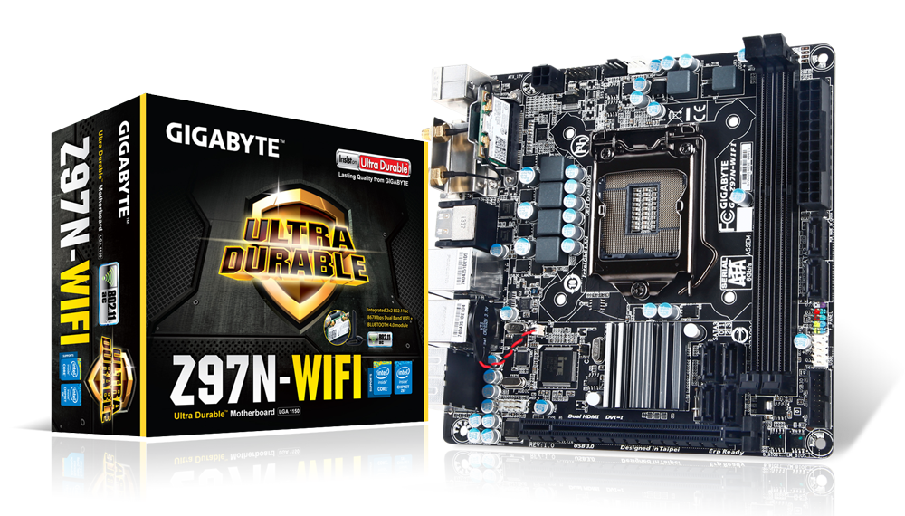
GIGABYTE Z97N-WIFI Visual Inspection
The immediate visual cues that separate the GIGABYTE Z97N-WIFI from the other two motherboards in this review is firstly the lack of a power delivery heatsink, and then the position of almost all the motherboard connectors around the outside of the PCB, including the 4-pin CPU power delivery.
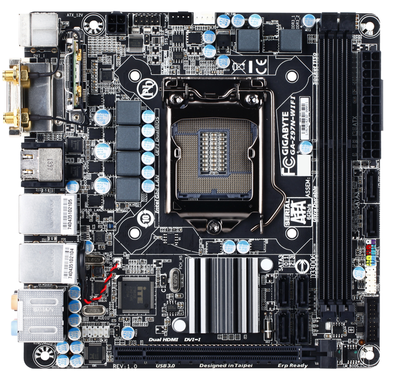
In the past, I criticized GIGABYTE for their component placement, but it would seem that the Z97N-WIFI gets a near perfect score. Along the top are the 4-pin CPU power connector, the COM header and the two fan headers, while on the right hand side (note, on the edge of the PCB) is the 24-pin ATX power connector, two of the SATA ports, the front panel header, a USB 2.0 header and a USB 3.0 header. Actually the only ports slightly away from the edge are the other four SATA ports, but given that two are on the outside that makes building a PC a lot easier.
The lack of a power delivery heatsink might give cause for concern for overclocking, however GIGABYTE is claiming to use high efficiency power delivery ICs and our overclock testing differs little from the other two motherboards.
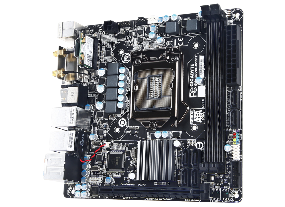
The mini-PCIe slot for the wireless module is near the rear panel which keeps the wires for the antenna very short and does not block any other headers on the motherboard. The two fan headers at the top of the motherboard might be a little localized, and perhaps another header on the right, or lower down the motherboard, might be well received.
The socket area is above the chipset for the GIGABYTE board, with the only barrier to large CPU coolers being tall DRAM modules, although with some regular or low profile modules it looks like this motherboard could cope with almost any large air cooler. To save space, GIGABYTE has stuck the motherboard battery to the rear panel, something we have seen in previous iterations.
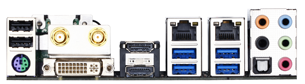
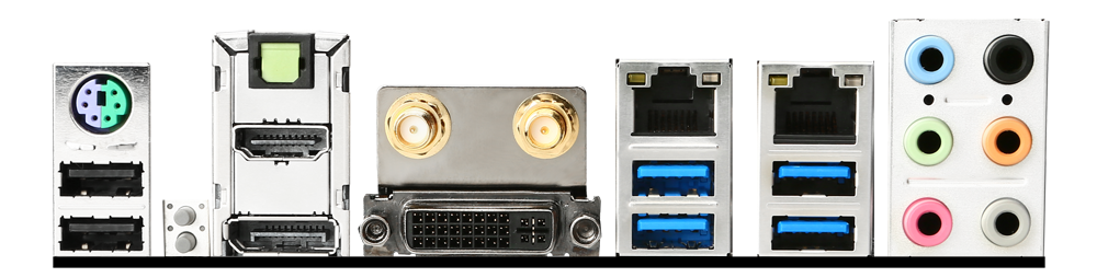
The rear panel of the GIGABYTE motherboard affords another difference to the other motherboards – two HDMI-out ports. This is backed up with a DVI-I, but no DisplayPort here. The panel also includes a combination PS/2 port, two USB 2.0 ports, four USB 3.0 ports, an Intel I217-V NIC, an Atheros AR81 NIC and the audio jacks (Realtek ALC892).
Similarly to the MSI, there are no PCIe storage options here, and the audio codec matches that of the MSI.
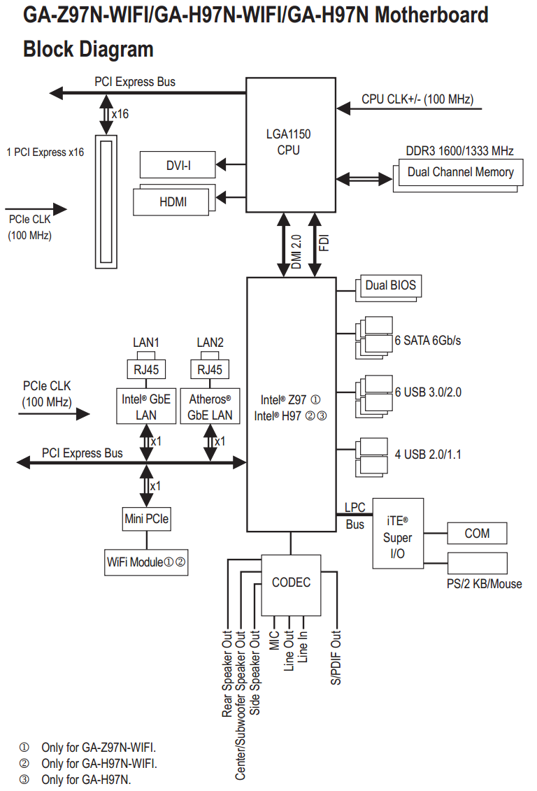
Unlike other manufacturers, GIGABYTE puts a block diagram of each motherboard in their manuals. Here we can see where all the PCIe lanes end up being distributed. Due to the limited size of mini-ITX, only a few are used.


38 Comments
View All Comments
pierrot - Wednesday, July 23, 2014 - link
Great article, you read my mind with this, Im planning on an ITX form factor for my next buildZap - Wednesday, July 23, 2014 - link
Do it! Unless you have a need for more than six HDDs or more than one graphics card there is little reason to go bigger and have a mostly empty case.Alternately there is also the little loved micro ATX. Not as "normal" as ATX and not as sexy as mini ITX, but IMO a very good alternative that gives you room for dual graphics, or some expansion cards.
PICman - Wednesday, July 23, 2014 - link
Excellent review. Every time I see a review of ITX boards I'm amused by the giant 2x24 power connector plus an additional 2x2 or 2x4. Every other connector on the original IBM PC has an updated version. Has there been any discussion of a smaller power connector?Aikouka - Wednesday, July 23, 2014 - link
I was working in a Dell workstation a few weeks back, and I was rather surprised to see that it didn't have a standard ATX power cable. Its power cable was probably about half the size, and if I remember correctly, the motherboard also provided a connector for a cable that provided power to the hard drive(s).I would definitely like to see someone be willing to revamp the power delivery as dealing with that monstrous cable is definitely my least favorite part -- especially on cases with too little room in the back!
DanNeely - Wednesday, July 23, 2014 - link
Dell's been using proprietary cables on/off for the last 20 years. I'm glad the current version uses different connectors though. IN the past they've had proprietary cables using AT or ATX standard sockets but with different pinouts so you'd smoke your hardware if you didn't realize it and tried to use a standard PSU as a replacement.DanNeely - Wednesday, July 23, 2014 - link
I've jumped on my soapbox more than once grumbling about the stupidity of a cable that mostly provides 3/3/5v power when the death of legacy PCI has removed the last significant 3.3v component and 5v is only still used for USB more than once in the comments here.But between the failure of BTX and the fact that the desktop market is generally seen as being in terminal decline I'm not optimistic about the likelihood of ever getting a 12V centric CTX PSU standard. If pigs ever do fly though, instead of mashing the entire 4/8pin 12v connector into the cut down remnant of the 24pin cable, I'd rather see the main connector only have enough 12V to run an full power CPU+IGP (or lower power CPU + discrete GPU) based system, with the extra power for a full power CPU and PCIe GFX card in a separate and optional cable: Both to keep cost down for lower end systems, and because the 24 wire cable is a major pain to route because of its thickness.
PICman - Wednesday, July 23, 2014 - link
While we're dreaming, we might as well make the voltage 24 or 48 V to reduce the current and improve the efficiency of the switching power supply.DanNeely - Wednesday, July 23, 2014 - link
Maybe...Just rationalizing the pinout would be a much lower impact change and could be done with adapter cables in both directions for reasonably current hardware (most of the 3.3/5v capacity in the 24pin is unused on both sides of the cable).
Unless PCIe refreshed to use the higher voltage as well (and for a number of transition years in any case) we'd still need to provide a lot of 12V power. The USB charging committee's one cable to bind them all goals include 5A@2v power (for faster tablet charging and for low power laptops) which'd bring an additional long term need for significant amounts of 12v into the system. They also want a 5A@20v step for mainstream laptops; so if we did shift to a higher DC voltage that might be a better option instead.
The_Assimilator - Friday, July 25, 2014 - link
24VDC or even better, 48VDC needs to become the new industry standard immediately. When you have a card like the 295X2 that requires 600W but can only pull that over a 12V line (=50 amps!!!), you have an obvious problem. It's one I fear only Intel can solve, the question is do they have the determination to do it?Personally I believe that the PC industry will embrace a new power delivery standard. It means everything will have to be redesigned, which means they get to sell more products. The successor to ATX (which is not BTX) could very well be the boost the PC industry's been looking for.
Mr Perfect - Thursday, July 24, 2014 - link
If they ever did change things, any reason why they couldn't just pump in one 12v plug and then let the mother board do DC-to-DC conversion for other voltages? Smaller embedded boards do this, but I don't know if it would scale up well.