GIGABYTE F2A85XN-WiFi Review: FM2 and Richland in mini-ITX
by Ian Cutress on August 21, 2013 10:00 AM ESTGIGABYTE F2A85XN-WiFi BIOS
Over the past twelve months, GIGABYTE has gone through an up and down motion with their BIOS and BIOS terminology – first we had 3D BIOS, with an image of a motherboard and an advanced mode. This was a little slow at the start, but GIGABYTE ironed out the issues, although 3D BIOS was not that well received. Fast forward to Z87, and we got a HD mode that gives smoother fonts and allowed customization. The BIOS used on the F2A85XN-WiFi is an odd hybrid, featuring neither 3D BIOS nor the HD mode, and focusing solely on the Advanced mode of the 3D BIOS and the Classic mode of the new BIOS.
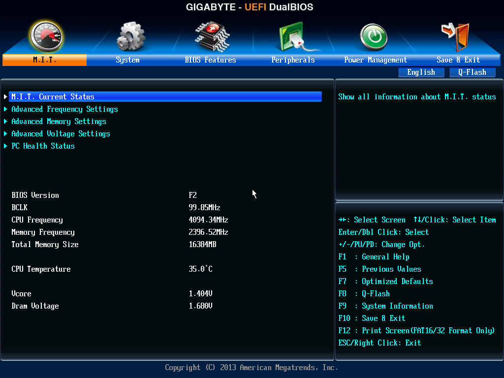
This means that our front page in the BIOS is our Advanced mode screen, showing basic details about the platform – BIOS version, BCLK, CPU frequency, memory size, CPU temperature and voltages. The key points that the front screen of the BIOS is missing is the Board SKU name, as well as the CPU installed.
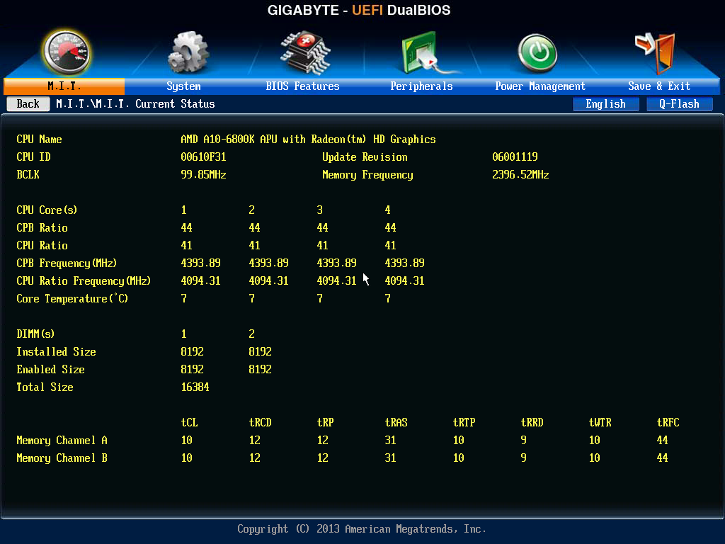
For the CPU installed, we have to navigate to M.I.T. Current Status, which shows the CPU ratios as well as memory settings. Notice in the screenshot below we have the CPB Ratio (AMD Turbo Boost), and that the Core Temperature is wrong – I am not running this CPU at 7C while taking the screenshot.
What the BIOS does give from the main screen is access to our main OC areas – Advanced Frequency, Memory and Voltage Settings. GIGABYTE prefers to split the BIOS into these separate components, rather than CPU/Memory/Power on the presumed basis that it helps divide the components that could damage the system from those that actually would. Ideally I would like to see some form of automatic overclock settings here for users to choose from (like in the HD BIOS), but for the time being users will have to rely on the EasyTune automatic overclock settings in the OS software.
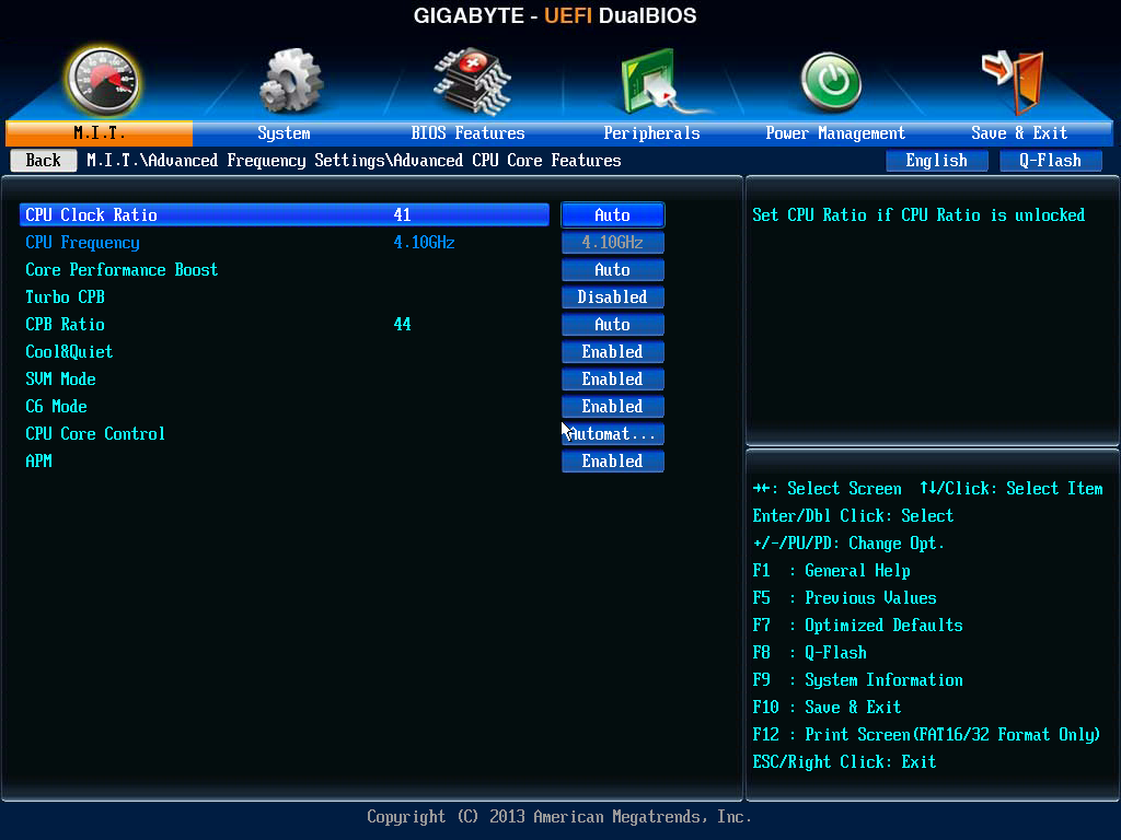
In the Advanced Frequency Settings menu we get our options for BCLK, NB, CPU core Ratio and enabling XMP/AMP. A couple of features users should be aware of – adjusting the BCLK by +10% also increases the NB and IGP graphics clock, although this is not shown. The second issue is that raising/lowering the CPU Clock Ratio needs to be performed in conjunction with the CPB Ratio under the Advanced CPU Core Features menu option.
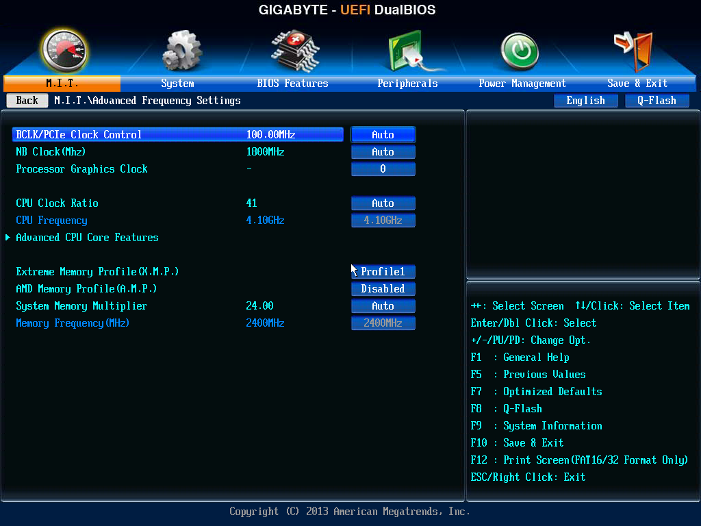
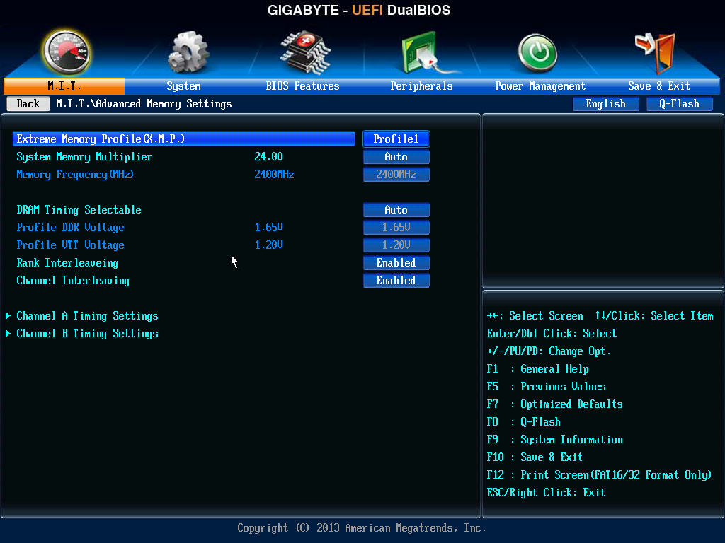
Even though there are two options for memory in this menu, XMP and AMP, I was able to use XMP on the AMD platform with my Corsair Vengeance Pro 2400 C10 memory kit without issue.
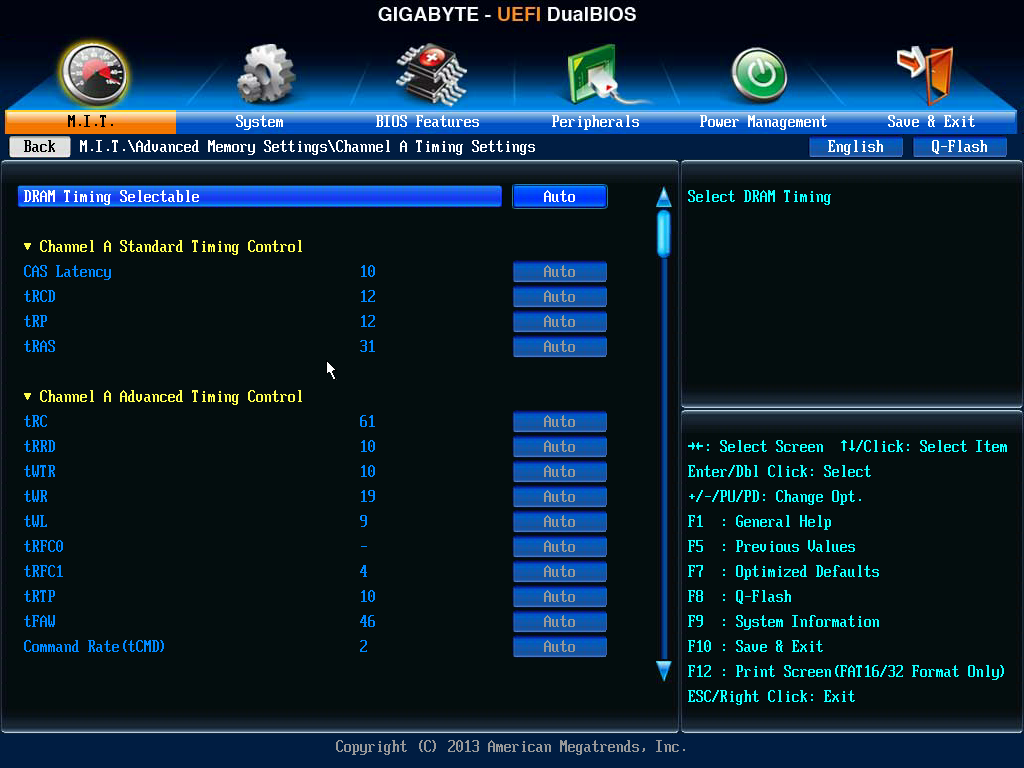
In the Advanced Memory Settings menu we have similar options to the frequency menu, although by selecting DRAM Timing to ‘Quick’ or ‘Expert’, this options up the sub-timings menus for manual adjustment:
The Advanced Voltage Settings menu does what it says on the tin – we get access to the CPU VCore, North Bridge voltages, DRAM voltage and load line calibrations. For the majority of motherboard implementations, this is all most users will need access to, perhaps with a graph to show what the options for LLC actually means. If a user needs more than this, then BIOSes should offer an ‘OC’ switch on board.
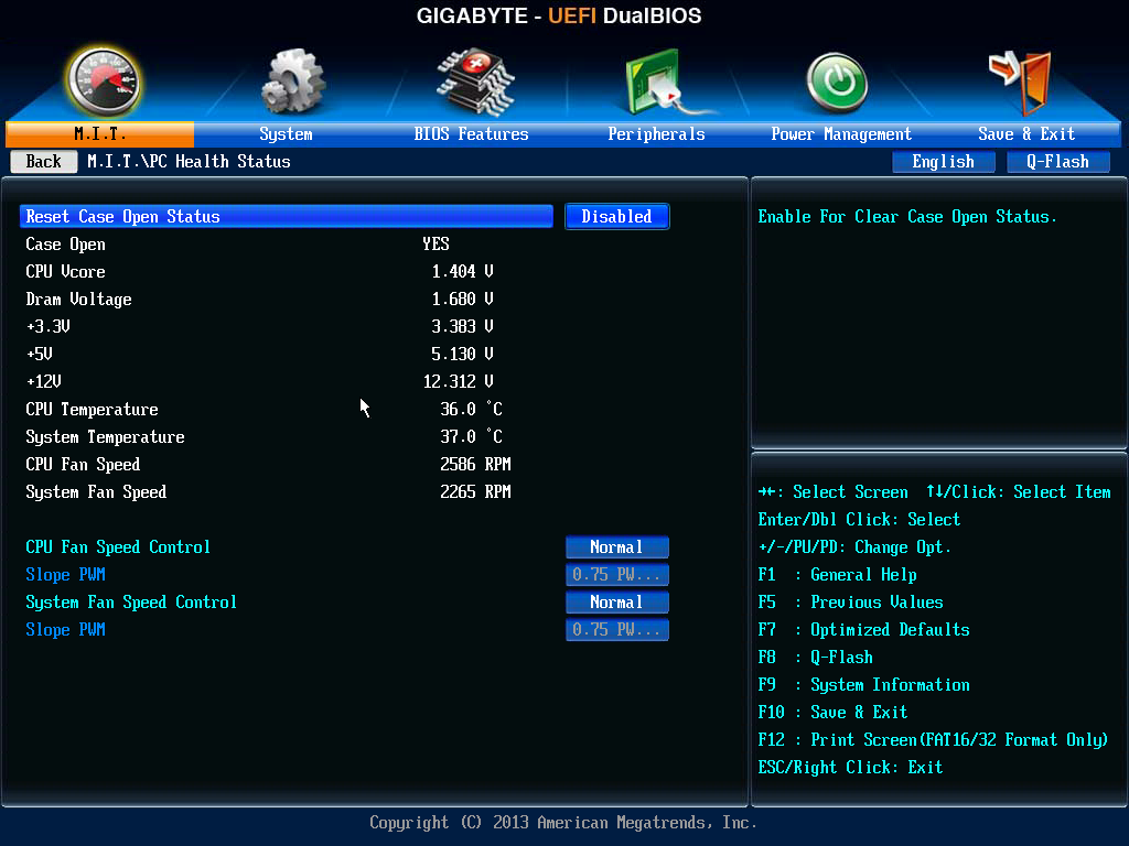
The PC Health Status screen contains all the voltage readouts, temperature sensor readings and fan speeds of the motherboard. Being a mini-ITX there is not an extensive array of values to look at, and the two fan headers have controls here as well. As mentioned in previous reviews, GIGABYTE’s fan controls in the BIOS are labeled in PWM/C, meaning that power is applied for every degree Celcius the system detects. This is an easy way out of providing fan controls, given that every fan has different characteristics and really users need to be able to define the idle and 100% points of the fan to begin with.
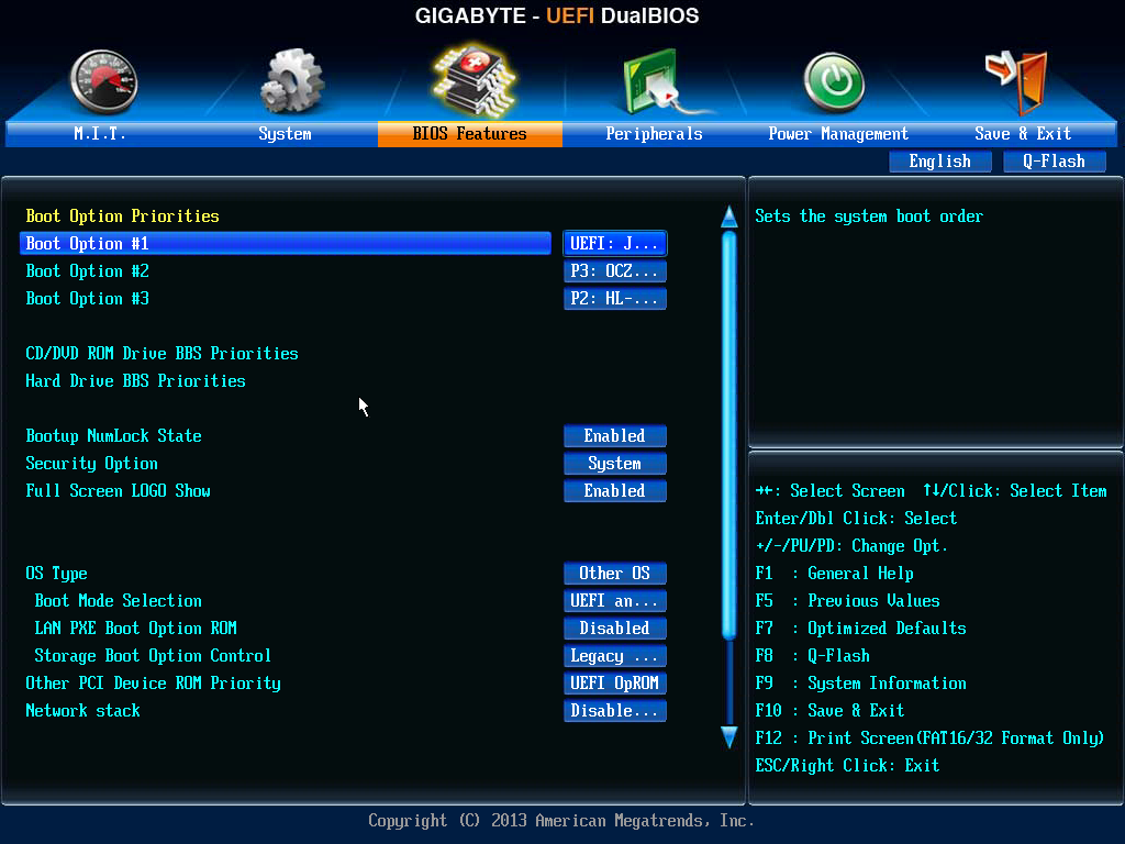
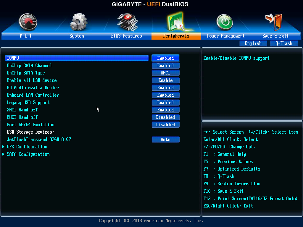
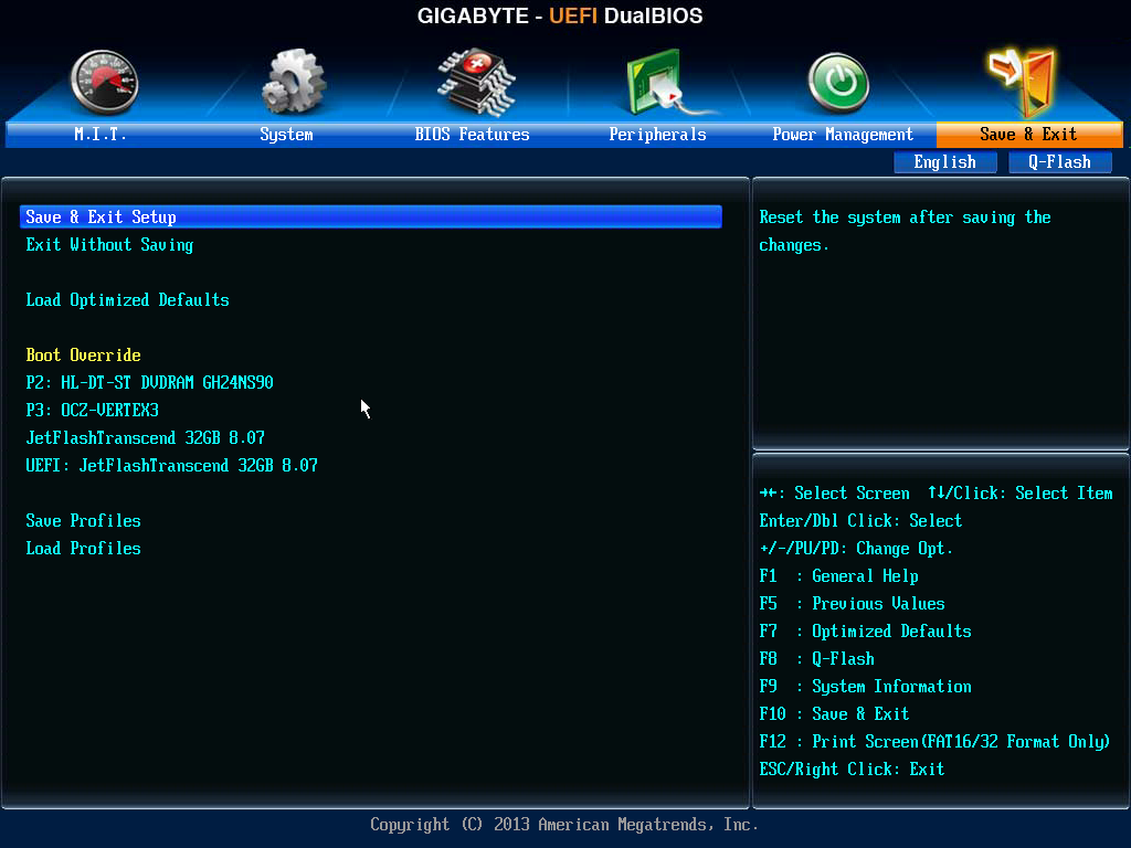
Elsewhere in the BIOS we have the regular array of BIOS features/boot options, options to enable/disable controllers or SATA type (IDE/AHCI/RAID), Boot Override and flashing the BIOS to a newer version.


GIGABYTE F2A85XN-WiFi Software
In our last GIGABYTE review, we got a chance to look at the latest version of EasyTune, and GIGABYTE’s way of molding all the additional features they have implemented in software over time into one package. Despite early beta version hiccups, it promises to be a software package that is fun to play with and will satisfy user requests. As the main focus of the year for most motherboard companies has been the Intel Z87 platform, that software was designed, in conjunction with hardware decisions made, on the 8-series. As a result, due to few updates on the AMD side in terms of socket/chipset, we still have the older EasyTune6.
It should be noted that the installation CD did not install EasyTune6 when it asked to install all applications – it had to be manually selected in the menu. At this point in time, the two main parts of the software on FM2 is EasyTune6 and @BIOS, the BIOS flashing utility. We also have the LAN Optimizer, which is a GIGABYTE skinned Realtek software solution to optimize the NIC for various workloads.
EasyTune6
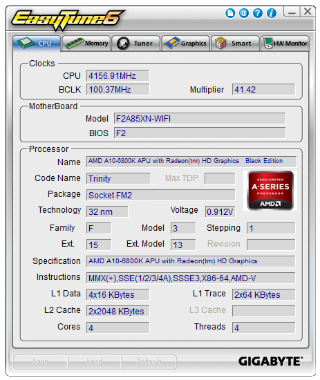
EasyTune has been with us in various guises over the years. The latest version is number six, which has been part of the main non 8-series GIGABYTE software package for at least two years now. The premise of EasyTune is simple – a single interface in order to get all the information about the system, perhaps do some overclocking, adjust some fan settings and monitor what is going in under the hood. Notice below it still detects the 6800K as Trinity rather than Richland:
A step up from our encounter with the F2A85X-UP4 is the inclusion of automatic overclock options. EasyTune6 offers its standard three modes of overclock, although the graphic and numbers displayed are different from other indicators on the image:
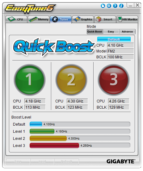
As shown we get three potential overclocks: 4.18 GHz (which is more an underclock), 4.3 GHz and 4.26 GHz – the key feature rising across these options is the BCLK, which affects the memory as well. We go over these settings in the overclock section of this review.
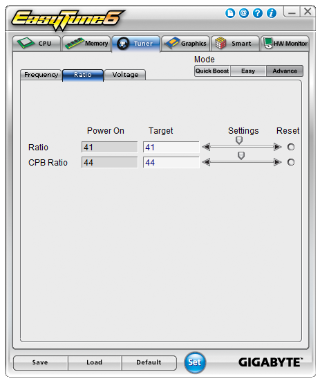
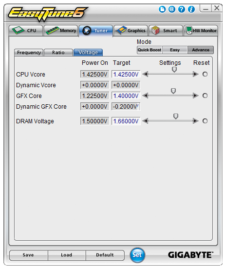
Users also have the option for manual overclocks by selecting ‘Advance’ at the top of the Tuner tab. Here we get multiplier and voltage control:
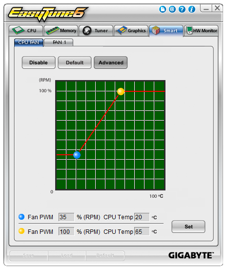
We can also control the fans in ET6, including manipulation of a gradient. This is only a two-point gradient, where the y-axis says RPM and the x-axis gives temperature. What is interesting is that below this are the actual numbers, whereby it says ‘Fan PWM, 35% (RPM)’. This is an erroneous statement – fan speeds are not directly proportional to the power applied. Typically a fan will start at a minimum RPM on low power, then after a threshold it will start to rise linearly. But not in the fashion that GIGABYTE’s software suggests.
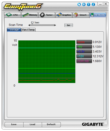
The final part of ET6 is the monitoring tool. This gives a small graphical output for voltages, although the scale of the graph could be frustrating as it tries to take into account low voltages such as the CPU along with the +12 V rail in the same graph. The default scan time of 3 seconds causes concern in our DPC Latency test, whereby we would score over 1000 microseconds when ET6 was running. This could lead to audio issues when recording, thus it is recommended to disable ET6 when audio processing. Also it is useful to note that the only effective way of monitoring the temperature of the CPU via software was in the Temp tab.
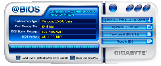
@BIOS
When it comes to updating the BIOS on a motherboard, there are two main different methods – through the BIOS itself, or in software. Typically I prefer the former via a USB stick, but in circumstances where that is not applicable, the software tool is the way to go. GIGABYTE has this pre-packaged into @BIOS which allows users to access the internet for the latest BIOS version, or upload from a file.
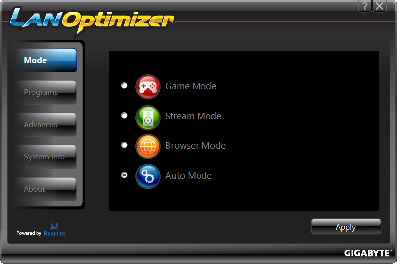
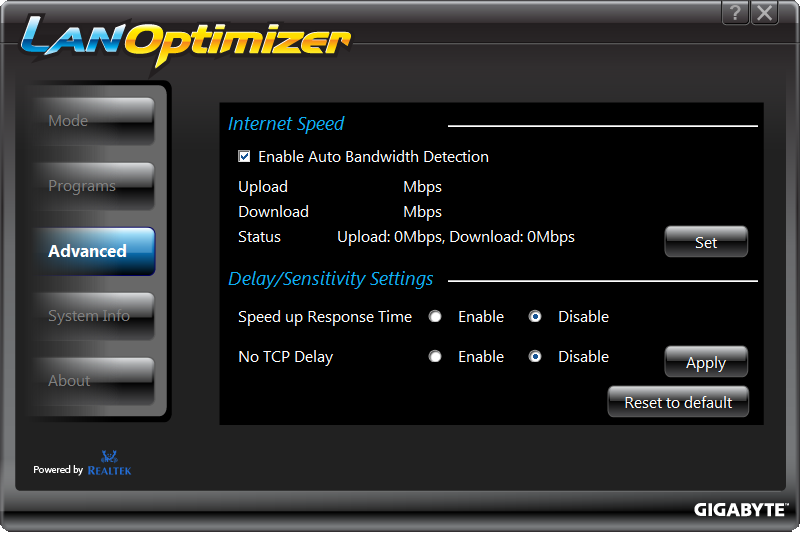
LAN Optimizer
A recognizable trend in motherboard manufacturer software packages over the past few years is the inclusion of ways to manage the traffic through the Ethernet ports. Depending on which NIC the motherboard has (Realtek, Intel, Atheros, Killer), some of these come with their own software for motherboard manufacturers to rebrand. Some motherboard manufacturers prefer to bulk-buy licenses to software that does it on any network interface at minimal cost to the end user. In the case of the F2A85XN-WiFi we get Realtek’s LAN Optimizer, which offers several modes (Game, Stream, Browser, Auto) which change the priorities of various pre-programmed lists of software. Users can add software to this list, in the hope that their software is not disturbed by background processes.


31 Comments
View All Comments
DanNeely - Wednesday, August 21, 2013 - link
Every time I look at the ultra-crowded layout of an mITX board I'm reminded of how dated the main 24 ATX power plug is and how much it would benefit from being replaced. While they were king in the p1 era with the CPU and PCI busses running on 3.3v directly and most other chips on the board designed for 5V; 3.3 and 5V are barely used at all any more but have 3 and 5 wires in the 24pin cable; while -5V has been removed entirely from modern versions of the spec. Dropping to a single 3.3/5v wire and removing the -5v one would free 7 pins directly; and with only 4 power pins left in the legacy connector (3.3, 5, 2 x 12) there's no need for 8 ground pins either. Probably we could drop 5 of them.This would allow for a successor cable that's only half as large; freeing space on crowded boards and replacing the 24wire cable with a 12 wire one that would be much less of a pain to route in a crowded case. I'm inclined to keep the CPUs 12V separate just to avoid trading one overly fat wire bundle for another and because AIUI the other half of why the CPUs 12V comes in separately is to get it as close to the socket as possible without crowding the area with everything else.
EnzoFX - Wednesday, August 21, 2013 - link
Yes, I've been saying this since ITX was taking hold. It is absurd how held back we are by entrenched standards. It's not in their business to reinvent.Jambe - Thursday, August 22, 2013 - link
I enjoyed this astute observation-comment.Right on.
That is all.
cjs150 - Friday, August 23, 2013 - link
Totally agree on the ATX cable.While we are at why do motherboards virtually never come with the ATX connector being at right angles rather than straight up - we get that for SATA connectors and it seriously improves cable management
flemeister - Friday, August 23, 2013 - link
Not such a good idea for mITX boards, when you might expect to install them in small cases such as the Antec ISK110 or Minibox M350. Right-angled ATX power or sata ports would be blocked off.How about RAM though? Why not use SO-DIMMs that are about 60% the size of regular DIMMs? They're readily available, and are priced the same or very close to the price of regular size RAM. Assuming two sticks of RAM, that would save even more room on the motherboard than a redesign of the 24-pin connector. Just look at the Asus P8H67-I Deluxe for an example. :)
DanNeely - Friday, August 23, 2013 - link
It's not just mITX boards that would have a problem with right angled ATX power sockets. Unless the PSU also included a right angle 24pin cable it would be problematic in any case that uses cable management holes to route the cables behind the mobo tray. Trying to make a 90* bend in that cramped a space would put a lot of torque on the socket; a big ugly loop sticking up allows for a much looser and less stressful bend.DanNeely - Friday, August 23, 2013 - link
For dimm sizes I think it's mostly a capacity issue. For more modest builds it probably doesn't matter; but higher capacities tend to come out a year or two sooner in full size dimms because you can jam more chips onto them if need be. Currently DDR3 dimms and sodimms both max out at 8GB for desktops; but if you're willing to pay the price premium server ram is available in up to 32GB dimms.flemeister - Saturday, August 24, 2013 - link
True, but how about SO-DIMMs on a budget Intel H81/B85 or AMD A55/A75 board? Or one of the low-power Intel Atom or AMD Brazos ITX boards? Or even a budget Z87 ITX board, to avoid the need for a vertically mounted VRM daughterboard (unless that's actually cheaper to do)? More space for surface mounted components, and probably cheaper to make the board? Could also mean less PCB layers?DanNeely - Saturday, August 24, 2013 - link
You're only saving 36 pins/dimm (204 vs 240); so there's no where near enough savings to drop a PCB layer. Beyond that I'd guess that since they do offer some models with SoDIMM slots that they just don't sell as well. If I had to guesses why it'd be that people are more likely to have spare DIMMs laying around than spare SoDIMMs; meaning that the total build cost is lower since the ram is free and/or the cost savings from larger DIMMs are enough to drive shoppers.The one configuration I could see driving some enthusiast/gamer consumption of SoDIMM based mITX boards would be 4 slots instead of only 2 for 32GB max instead of 16; is conspicuous by its absence.
Hyoyeon - Wednesday, August 21, 2013 - link
You mention DisplayPort several times, but this board does not have a DP connector. Where did this come from?