ASRock B550 Taichi Review: The $300 B550 Motherboard with Chutzpah
by Gavin Bonshor on August 21, 2020 3:30 PM EST- Posted in
- Motherboards
- AMD
- ASRock
- Taichi
- AM4
- Ryzen 3000
- Ryzen 3700X
- Ryzen 4000
- B550
- B550 Taichi
Power Delivery Thermal Analysis
One of the most requested elements of our motherboard reviews revolves around the power delivery and its componentry. Aside from the quality of the components and its capability for overclocking to push out higher clock speeds which in turn improves performance, is the thermal capability of the cooling solutions implemented by manufacturers. While almost always fine for users running processors at default settings, the cooling capability of the VRMs isn't something that users should worry too much about, but for those looking to squeeze out extra performance from the CPU via overclocking, this puts extra pressure on the power delivery and in turn, generates extra heat. This is why more premium models often include heatsinks on its models with better cooling designs, heftier chunks of metal, and in some cases, even with water blocks.
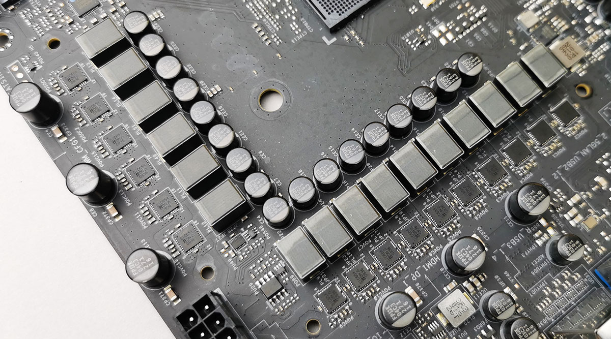
The 16-phase power delivery operating at 7+1 on the ASRock B550 Taichi
Testing Methodology
Out method of testing out if the power delivery and its heatsink are effective at dissipating heat, is by running an intensely heavy CPU workload for a prolonged method of time. We apply an overclock which is deemed safe and at the maximum that the silicon on our AMD Ryzen 7 3700X processor allows. We then run the Prime95 with AVX2 enabled under a torture test for an hour at the maximum stable overclock we can which puts insane pressure on the processor. We collect our data via three different methods which include the following:
- Taking a thermal image from a birds-eye view after an hour with a Flir Pro thermal imaging camera
- Securing two probes on to the rear of the PCB, right underneath CPU VCore section of the power delivery for better parity in case the first probe reports a faulty reading
- Taking a reading of the VRM temperature from the sensor reading within the HWInfo monitoring application
The reason for using three different methods is that some sensors can read inaccurate temperatures, which can give very erratic results for users looking to gauge whether an overclock is too much pressure for the power delivery handle. With using a probe on the rear, it can also show the efficiency of the power stages and heatsinks as a wide margin between the probe and sensor temperature can show that the heatsink is dissipating heat and that the design is working, or that the internal sensor is massively wrong. To ensure our probe was accurate before testing, I binned 10 and selected the most accurate (within 1c of the actual temperature) for better parity in our testing.
For thermal image, we use a Flir One camera as it gives a good indication of where the heat is generated around the socket area, as some designs use different configurations and an evenly spread power delivery with good components will usually generate less heat. Manufacturers who use inefficient heatsinks and cheap out on power delivery components should run hotter than those who have invested. Of course, a $700 flagship motherboard is likely to outperform a cheaper $100 model under the same testing conditions, but it is still worth testing to see which vendors are doing things correctly.
Thermal Analysis Results
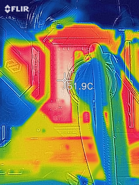
We measured 51.9°C on the hottest part of CPU socket area during our testing
The ASRock B550 Taichi is using a 16-phase design which is operating in a 7+1 configuration with an Intersil ISL229004 8-phase PWM controller. It is using fourteen Vishay SiC654 50 A power stages for the CPU and two SiC654 50 A power stages for the SoC. The CPU section is using seven ISL6617A doublers, while the SoC section is using a single ISL6617A doubler which makes the B550 Taichi's power delivery a 7+1 design. The power delivery is cooled by a pair of heatsinks connected by a single heat pipe which relies on passive airflow within a chassis.
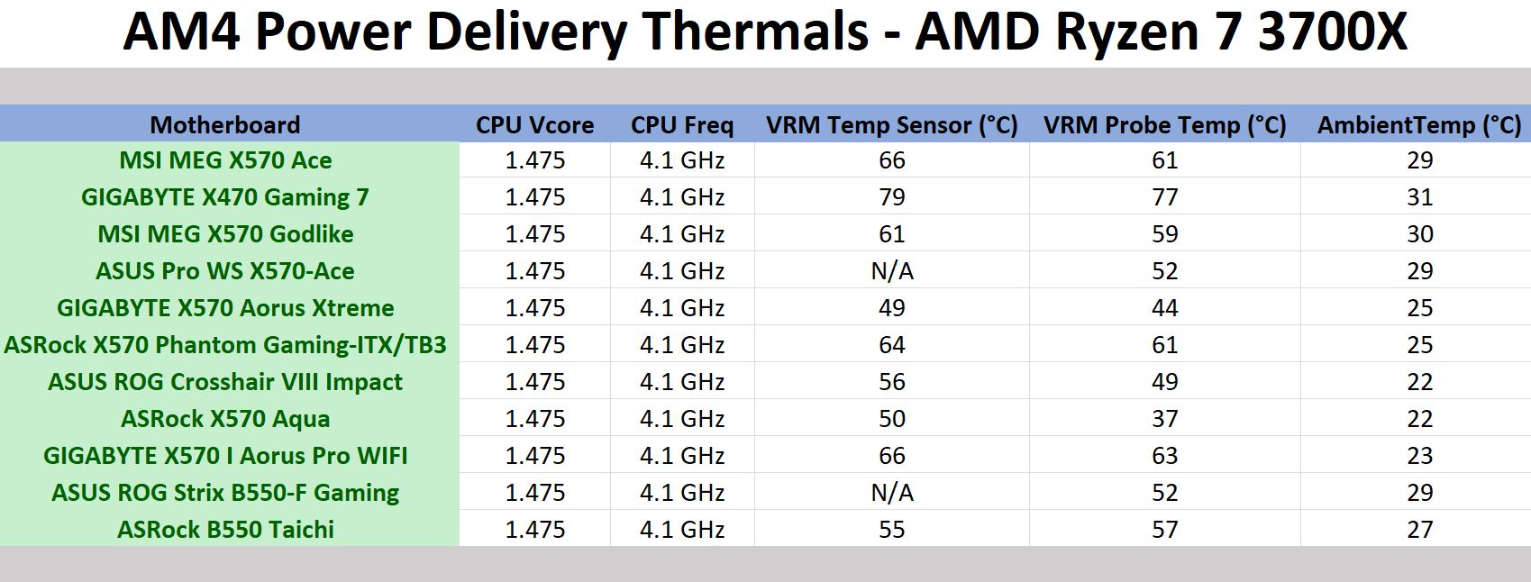
In our power delivery thermal testing, the ASRock B550 Taichi performs quite well against other AM4 boards on test. Our testing shows that the Taichi's 16-phase design is rather efficient, which puts it ahead of some high-end X570 models which is impressive. The Taichi includes a dedicated temperature sensor for the power delivery which in our testing displayed a reading of 55°C, while our K-type probe mounted to the rear of the power delivery measured a reading of 57°C. Using our FLIR thermal imaging camera, we measured a 51.9°C on the hottest part of the CPU socket area, which shows that the cooling properties of the heatsink is efficient at dissipating heat. For a B550 motherboard, the results are competitive, and that the ASRock B550 Taichi is a very competent board for overclocking.


61 Comments
View All Comments
Gigaplex - Saturday, August 22, 2020 - link
I just bought a B550 motherboard. It was 30% cheaper and had features that the X570 version didn't have (eg 2.5Gbit ethernet, better accoustics due to lack of a chipset fan).WaltC - Saturday, August 22, 2020 - link
$360 x570 Aorus Master is a far better buy. BTW, I've never heard the chipset fan even once. Got a lot more features than this B550 mboard. Had my x570 AM over a year and its doing great--and I still haven't seen anything better on the market--other than the Xtreme--which for me would be overkill and cost 2x as much.kkilobyte - Sunday, August 23, 2020 - link
Except when the Aorus Master suddenly refuses to boot, requiring you to remove the CMOS battery to revive it. Which is something that happens a bit too often - and Gigabyte still unable to solve the issue.Showtime - Monday, August 24, 2020 - link
When going AMD, they get you on the motherboards. You also need more expensive ram to maximize performance. I was interested in AMD this round, but the Intel non k chips give the same,or better gaming performance, and actually come out to the same or less depending on motherboard, and ram. $200+ b series mobo's are just bad investments IMO.yannigr2 - Friday, August 21, 2020 - link
Would you please check something about B550 X570 boards?Here the Taichi has the option to drive both top PCIe x16 slots from the CPU. IF I am not mistaken.
On the other hand the majority of B550 AND X570 boards seems to connect only the first PCIe x16 slot on the CPU and EVERYTHING ELSE on the chipset. Even if they have 2 or 3 PCIe x16 slots. That means that in many cases ports get disabled when other ports are populated.
hetzbh - Friday, August 21, 2020 - link
No AM4 based can drive 2 PCIe X16 from the CPU (I wish..) since the Ryzen 2xxx/3xxx has 24 PCIe lanes out from the CPU. 4 goes to the chipset, 4 goes to NVME M.2, and the last 16 goes to the first PCIe slot and can be shared (X8/X8) between 2 slots, but no X16/X16.yannigr2 - Friday, August 21, 2020 - link
I wasn't talking about driving two PCIe x16 ports. I was talking about splitting those 16 lanes to a typical x8 / x8 configuration.While this was the obvious case in most AM3 motherboards for example, in many cases, even with x570 boards with two or three PCIe X16 slots, only the first slot is connected to the CPU. The second (and third is their is one) PCIe x16 together with the couple x1 ports are connected in the Chipset. So you read. If you connected something in the second M2, you lose that PCIe slot. If you connect something in that PCIe slot, you lose the other PCIe slot and etc.
yannigr2 - Friday, August 21, 2020 - link
One example of a 570 that does thisASUS PRIME-X570-P
https://www.asus.com/Motherboards/PRIME-X570-P/spe...
1 x PCIe 4.0 x16 (x16 mode)
AMD X570 chipset
1 x PCIe 4.0 x16 (max at x4 mode)
3 x PCIe 4.0 x1
So, form the two PCIe x16, only the first is connected to the CPU. The second is connected on the chipset.
You have a microATX motherboard disguised as a full ATX.
Hyoyeon - Friday, August 21, 2020 - link
In order to bifurcate the x16, boards need some logic to mux/demux the lanes. Switching up to nearly 32 GB/s of traffic is quite hard, and so the IC's are surprisingly expensive (especially when you get into the really fast things like PCIe 5/6).eddman - Saturday, August 22, 2020 - link
That information can be gathered from the product's page on their website. The following is from this board's page:"single at Gen4x16 (PCIE1)
dual at Gen4x8 (PCIE1) / Gen4x8 (PCIE3)
triple at Gen4x8 (PCIE1) / Gen4x8 (PCIE3) / Gen3x4 (PCIE5)"
They don't specifically mention exactly which slot is connected to what, but from the above info it's apparent that the first two x16 slots are connected to the processor, because the lanes are split when two cards are inserted. The third slot is obviously connected to the chipset.
The Asus example you posted below clearly states the second slot is connected to the chipset.