SSD Form Factors Proliferate At Flash Memory Summit 2018
by Billy Tallis on August 17, 2018 9:30 AM EST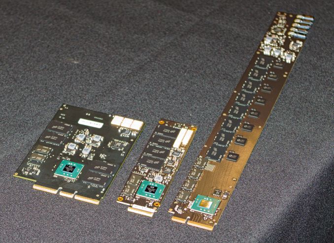
Last year, Intel and Samsung proposed new form factors for enterprise/datacenter SSDs with the goal of overcoming the shortcomings of the existing M.2, U.2 and PCIe add-in card form factors. Samsung's NF1 form factor (previously known as NGSFF) had little presence at Flash Memory Summit this year without Samsung's participation in the show, but the derivatives of Intel's Ruler design were all over the place. Unfortunately, the Ruler has spawned not just one industry standard, but a whole family of new form factors.
Working with SFF, the committee originally formed to standardize the 2.5" hard drive form factor, Intel's Ruler has led to the Enterprise and Datacenter SSD Form Factor (EDSFF) family of standards.
Why new form factors?
The existing form factor options for enterprise SSDs have proven inadequate for datacenter needs. It is increasingly common for servers to use several types of SSD (boot drive, performance tier, capacity tier), and that usually requires using more than one SSD form factor. Each has its own downsides:
2.5" SATA, SAS, U.2: Drives with the same 7mm thickness that consumer SATA drives use are relatively limited in maximum PCB area for NAND flash packages, and internal volume for power loss protection capacitors. Increasing the thickness up to 15mm allows for bulky capacitors and two PCBs stacked inside the drive's case, but this severely compromises the ability to cool the drive. Backplanes for 2.5" drives tend to be a severe airflow obstruction.
PCIe add-in cards: Half-height half-length (HHHL or MD2) cards have plenty of PCB surface area for large amounts of flash and heatsinks that can handle 40W or more. Full-height cards increase these limits even more. This is the only current option for PCIe x8 or wider interfaces. Hot-swapping is possible with many cards, but this does little good when the cards are not accessible from the front of the server.
M.2: Enterprise SSDs typically use the M.2 22110 card size that is longer than the 2280 card used by client/consumer drives. The extra space allows for higher drive capacities or power loss protection capacitors. However, the power and thermal limits are still severely constraining. Delivering more than 8W with only a 3.3V supply requires careful system design to ensure that enough current can be provided without the voltage dropping out of the required 5% tolerance. Dissipating 8-12W usually requires heatsinks that detract from the density advantage of such a small form factor. Hot-swapping is only possible by installing M.2 drives in some form of carrier module that further inflates the space occupied by each drive.
The SFF-TA-1002 Connector
The EDSFF family of SSD form factors share a common connector standard, which has also been adopted by the GenZ interconnect and the Open Compute Project's latest NIC form factor. The SFF-TA-1002 connector standard defines a multi-lane card-edge connector with a much smaller contact pitch than PCIe add-in card slots. Three sizes are defined, allowing for PCIe x4, x8 and x16 links, and narrower sockets can accept longer cards thanks to the notches in the card edge connector. The connector provides adequate signal integrity for data rates of at least 56 GT/s with a NRZ encoding (as used by PCIe) so it is more future-proof than most implementations of the existing connector standards for PCI Express signals. The smallest 1C variant allowing for PCIe x4 and power is 23.88mm wide, about the same size as a M.2 connector. The widest 4C variant supporting PCIe x16 links is 57.02mm, compared to about 89mm for a standard PCIe x16 slot.
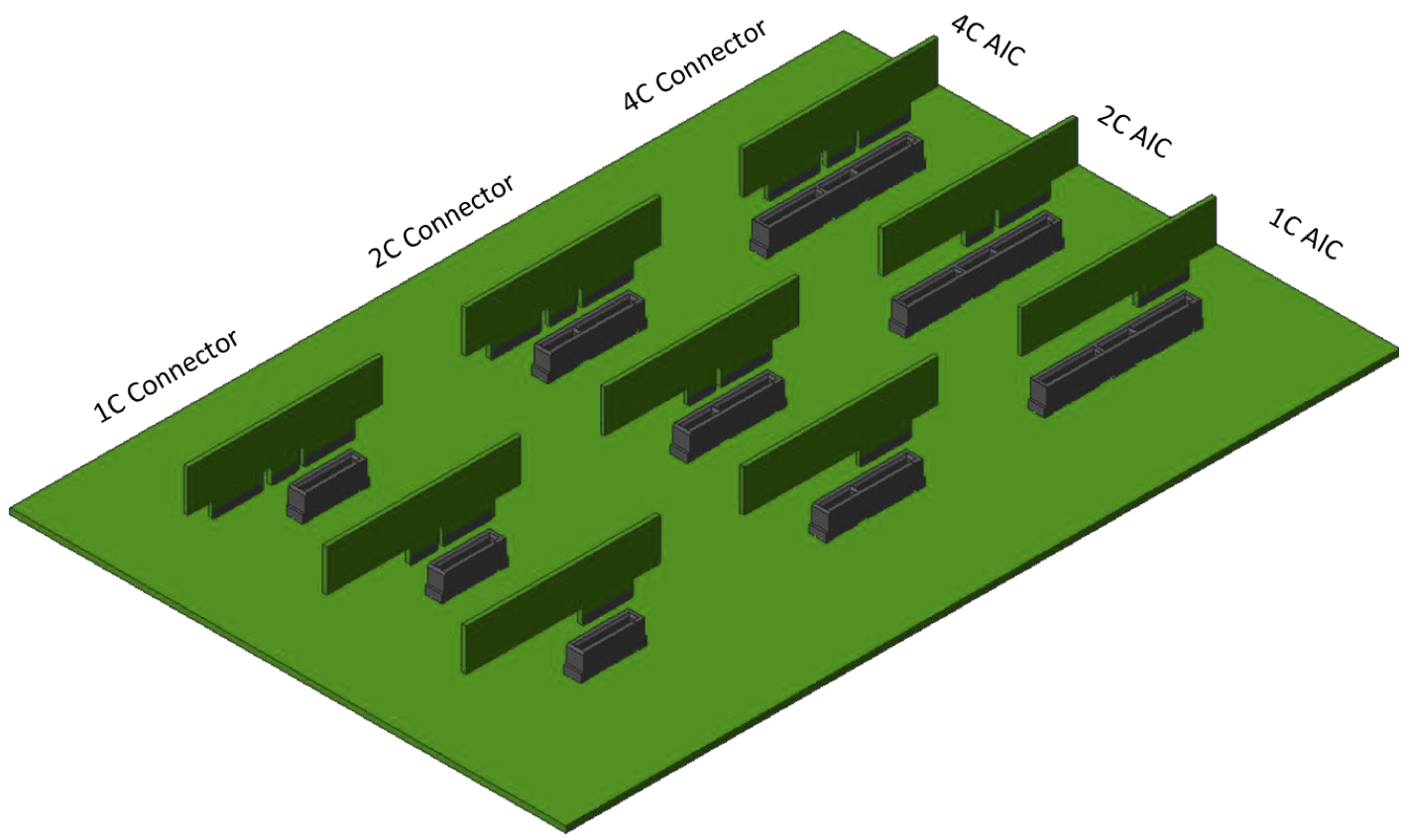
SFF-TA-1002 Connector and Card compatibility
More important than the compact size of the connector is how a backplane full of them is constructed. The EDSFF form factors are intended to be used with right-angle style connectors that result in the backplane PCB being parallel to the bottom of the server with air flowing across it, instead of being oriented to block airflow and requiring holes to be cut in the PCB to get effective cooling. The end result is that a 1U EDSFF drive bay for drives up to 8mm thick allows more airflow than a typical 2U bay for 2.5" drives. There are still surface-mount host side connectors that would be used with a more typical backplane arrangement, but the airflow advantages of the right-angle connectors are very compelling.

The actual pin-out is defined in SFF-TA-1009, which also specifies a 12V supply providing up to 70W per slot, plus a 3.3Vaux supply. This is close to the 75W that PCIe x16 slots can provide, and far more than the typical limits for any other drive form factor. The EDSFF form factors also specify that status LEDs are to be provided by the drive itself, controlled through a dedicated pin on the drive connector rather than being a component on the backplane shining through light tubes on a drive caddy.
EDSFF 1U Short and Long Rulers
Intel's original Ruler proposal was targeted at 1U servers, with the intention of allowing for at least 32 drives to be mounted vertically in the front of a server. The first Rulers that Intel showed off were over 12" long, requiring drive cages far deeper than for any existing form factor. Many servers designs don't want or need to dedicate that much internal volume to storage, so a shorter variant has also been standardized and seems likely to be more popular. The EDSFF 1U Short form factor is defined in SFF-TA-1006 and the 1U Long version is in SFF-TA-1007. The 1U Short is most similar to M.2 and Samsung's NF1 form factor. Like NF1, the 1U Short form factor features a wider card than M.2, allowing for two rows of NAND flash packages. 1U Short drive thickness is limited to 5.9mm or 8mm with a heatspreader, and this form factor is intended for drives up to about 12W. 1U Short drives have mounting holes in the corners and need to be installed in caddies for use in a typical hot-swap bay. Up to 36 of these drives can fit into the front of a 1U server.
The 1U Long form factor is more than just a stretch of the 1U Short. The corner mounting holes are replaced by the expectation that the drive include its own case and latching mechanism at the front. Two thicknesses are defined: 9.5mm for drives up to 25W, and 18mm for drives up to 40W. While 2.5" drives that thick often use two stacked PCBs, the extra thickness of 1U Long drives is intended solely for heatsink fins and both sides of the drive have the same clearance for their heatsinks.
EDSFF 3" (2U) Form Factors
Moving back toward traditional drive form factors, a set of 3" drive form factors has been defined, allowing for vertical mounting in a 2U server or horizontal mounting in a 1U server. The two lengths correspond roughly to that of 2.5" and 3.5" hard drives and are intended to allow for hot-swap cages of the same overall sizes. Drives can be either 7.5mm or 16.8mm thick, slightly thicker than the most common thicknesses for 2.5" drives. Like 2.5" and 3.5" drives, the EDSFF 3" form factors include a full casing around the drive, with the PCB mounted almost flush against one side of the drive instead of centered as in the 1U form factors.

source: SFF-TA-1008 revision 1.0
Hot-swap caddies are needed to provide a latching mechanism, but like the 1U form factors the 3" drives provide their own status LEDs. The drive-to-drive spacing is defined such that the two thicknesses can be mixed, and a 16.8mm thick drive can be inserted in place of two 7.5mm thin drives. A 1U server can fit 20 of the thinner 7.5mm drives, arranged as five stacks of four drives. Using 2.5" SSDs it is hard to achieve this density because of the bulkier connector. A 2U server with the drives in a vertical orientation can fit about 44 of the thinner drives.
The recommended power and thermal limits for the 3" form factors varies from 20W for the short/thin size up to 70W for the long/thick size. The drives can use any of the three connector sizes, supporting up to PCIe x16.


| SSD Form Factor Comparison | ||||||
| Form Factor | Approximate Dimensions (mm) |
Typical SSD Power Limit |
||||
| 2.5" U.2 | 70 | 100 | 7-15 | 25 W (15mm) | ||
| 3.5" | 102 | 147 | 26 | |||
| PCIe HHHL | 68 | 168 | 19 | 40-75 W | ||
| M.2 22110 | 22 | 110 | 5 | 8.25 W | ||
| EDSFF 1U Short | 32 | 112 | 6-8 | 12 W | ||
| EDSFF 1U Long | 38 | 319 | 9.5 | 25 W | ||
| 38 | 319 | 18 | 40 W | |||
| EDSFF 3", 7.5mm |
Short | 76 | 105 | 7.5 | 20 W | |
| Long | 76 | 142 | 7.5 | 35 W | ||
| EDSFF 3", 16.8mm |
Short | 76 | 105 | 16.8 | 40 W | |
| Long | 76 | 142 | 16.8 | 70 W | ||
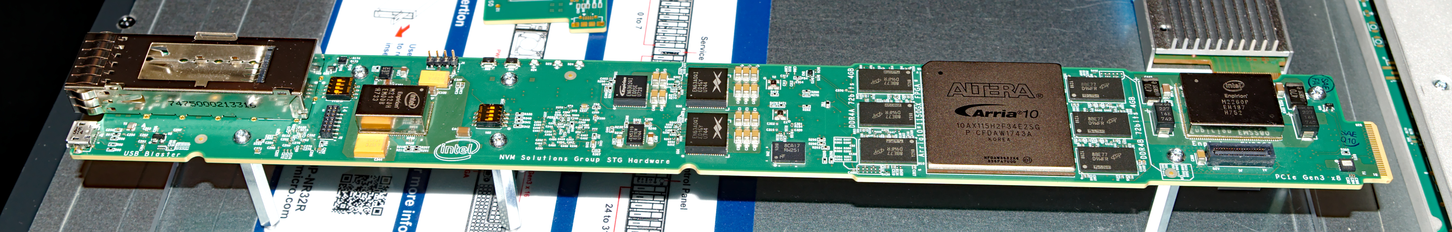
Almost all of the EDSFF hardware on display at Flash Memory Summit was using the 1U drive sizes. It appears that the 1U Short size will be the most popular, and the 1U Long will mostly be reserved for storage-oriented servers and JBOF enclosures. However, Intel did demonstrate a 1U Long accelerator card using a large Altera FPGA, taking advantage of the extra power and cooling provided by the thicker 1U Long variant.
The 3"/2U form factors are most likely to be used by servers designed to support a flexible mix of storage and compute/accelerator modules. The thicker 3" form factors could also potentially expose I/O connectors on the front of the server for things like network cards, but the current standard doesn't have anything to say about such applications.

1U Long quad M.2 carrier board with Marvell 88NR2241 NVMe Switch
Microsoft Azure has been using pre-standard 1U Long Ruler cards as carriers for 4 M.2 drives in some of their systems, but the complexity makes those merely a short-term transitional solution. They have qualified one native EDSFF 1U Long SSD and put it into production, and are working on qualifying three more drive designs in that form factor. They are also looking into using the largest 3" form factor as a replacement for PCIe HHHL cards. HPE is considering adopting the 3" form factor for their next generation of servers, and many other vendors are keeping an eye on the EDSFF standards but have been less specific about their plans.
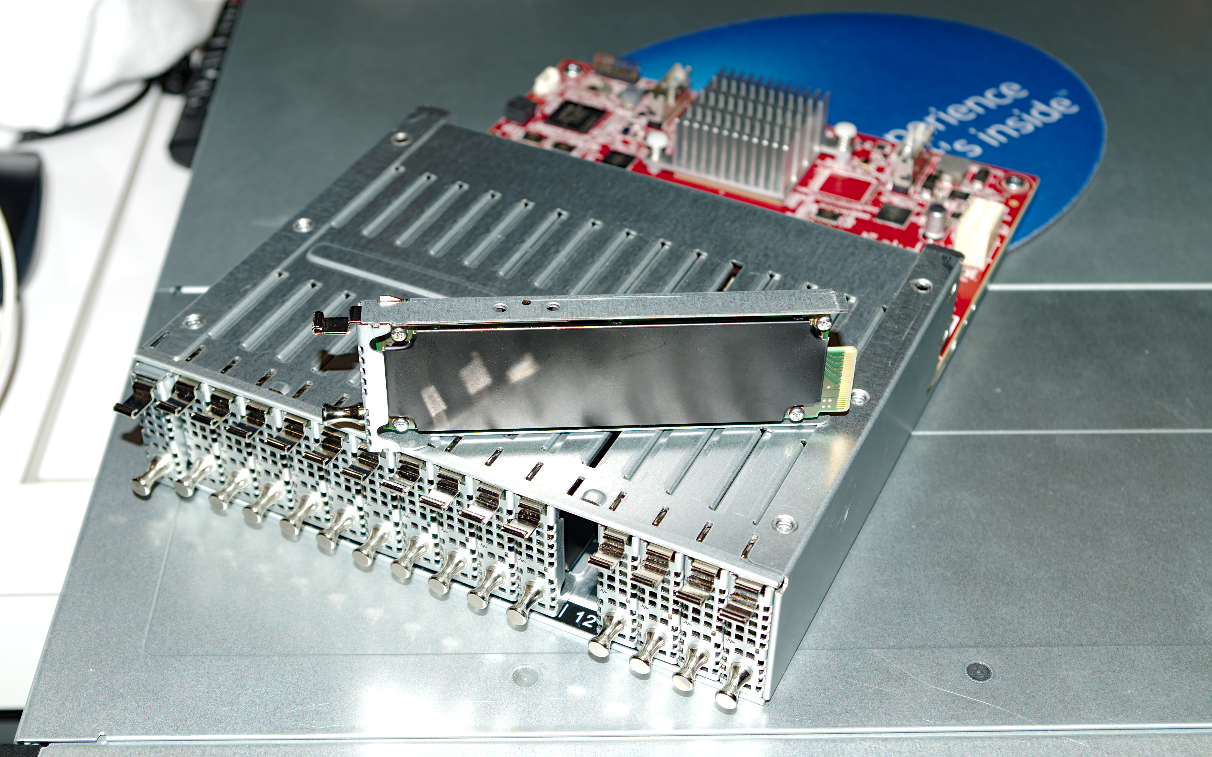
The servers on display at FMS did not all use EDSFF form factors exclusively. We saw a 1U server with traditional 2.5" bays, but the last two bays had been replaced by a 6-drive bay for EDSFF 1U Short drives.


26 Comments
View All Comments
RU482 - Friday, August 17, 2018 - link
too many options. this is why we can't have nice thingsdark4181 - Friday, August 17, 2018 - link
That's why the SFF-TA-1002 connector is so important when paired with SFF-TA-1006 and SFF-TA-1007. Once that's the industry standard we'll see more dense rack servers and more variable composable infrastructure. My employer is about to launch something that sets the foundation for this. Gonna be rad. The 3" variables are just a stopgap in the composability roadmap; they're far to space inefficient in the long term.edzieba - Friday, August 17, 2018 - link
I'd love to see this come to consumer devices, but I can't see see it getting around the legacy formfactor problem.wintermute000 - Friday, August 17, 2018 - link
yeah with flash prices supposed to be falling next year it would be nice to be able to build an all-flash prosumer class home server/NAS without the spaghetti of SATA and power cablingLonyo - Saturday, August 18, 2018 - link
Cabling does allow more flexibility in case design though, and also in using the slots for other things. If you want you can connect a 3.5" drive or 2.5" drive (SSD or mechanical) to the same port, which provides far more flexibility for consumer use/construction. If you want lots of flash storage, is there a problem loading up with PCIe drives or PCIe adapters for M2 devices?Lonyo - Saturday, August 18, 2018 - link
https://www.pcgamer.com/asus-has-a-motherboard-tha...CheapSushi - Friday, August 17, 2018 - link
I love when stuff like this happens. It's not often that new form factors get teased out with everyone having an idea of what it should or could be.Samus - Friday, August 17, 2018 - link
The problem is the inferior but less expensive technology always wins...at least in the consumer space.dark4181 - Friday, August 17, 2018 - link
I honestly don't think that'll happen this time. There are a lot of tech companies on board with Gen Z, and the trends in the industry are toward open systems. I'm hopeful that this will win out. Granted, at the consumer level it'll take 5-10 years, but I'd expect infrastructure level to be 2-3 years (based on my limited knowledge and speculation.)takeshi7 - Friday, August 17, 2018 - link
And I'm just waiting for normal consumer PCIe x8 SSDs to become a common form factor since many motherboards split the PCIe lanes into x8/x8.